


Application examples Household items

DEPRAG – For fully automated and efficient production
Assembly of geared motors for vacuum cleaner brushes
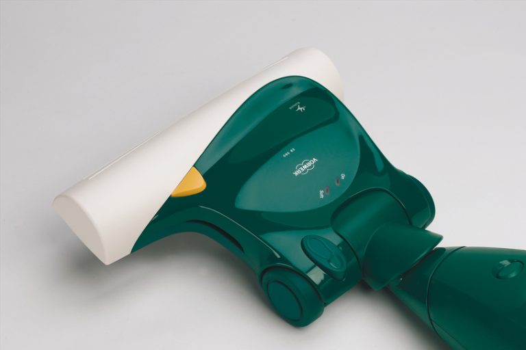
Process required:
Automatic station for notching and insertion of the adapter press during assembly of the electric vacuum cleaner brush motor and reducer. This station is part of a complete assembly line, where all individual stations are connected by a transfer system. The communication of the transfer system is handled by a read/write system. The read/write system ensures that each process includes the necessary operating steps and confirms it at the next station.
With an 8-position index rotary table with 6 processing stations, a total cycle time of less than 10 seconds per part was achieved.
This assembly system incorporated two Vibratory Feeders from the DEPRAG standard program, which are equipped with a partial monitoring camera system (recognizes left or right conveyor thread) that verifies accurate position sorting. Two belt-driven hoppers with a capacity of 10 liters each ensure optimum parts supply.
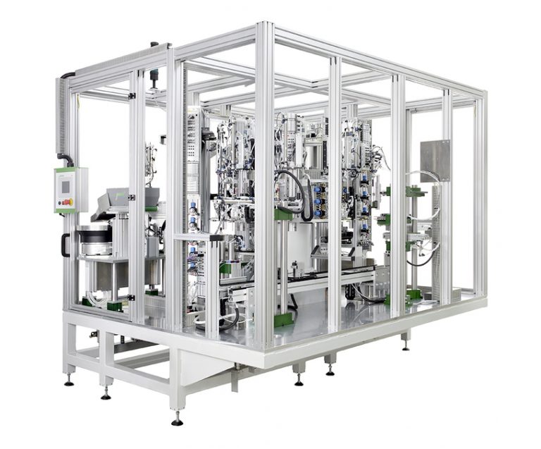
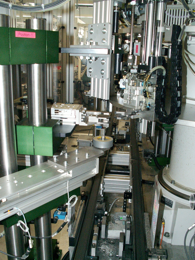
Station 1: Delivery
The geared motor is automatically removed from the pallet of parts and inserted into the workpiece holder of the index rotary table.
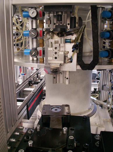
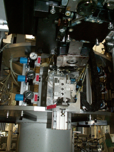
Station 2: lower notch
The shaft is placed in the notching tool and notched from below 4 times. The depth of the notch can be adjusted by means of stops on the notching tool.
Station 3: upper notch
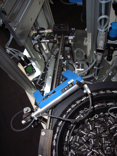
The shaft is placed in the notching tool and notched from above 4 times. The depth of the notch can be adjusted by means of stops on the notching tool.
Station 4: winding of the lower seal
A vibratory feeder feeds one catch at each station. A camera system verifies that the catch with right-hand thread is present in the transfer area.
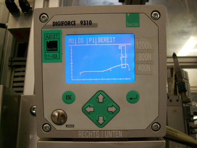
A catch that has a left-hand thread is automatically rejected. Using a vacuum handling system, the catch is placed in the winding unit. The winding process of the latch onto the shaft is verified by a force/distance measuring system (Digiforce 9310) and the curve is displayed graphically.
Station 5: winding of the upper latch
Sequence according to the image description of Station 4:
The process of winding the latch onto the shaft is verified by a force/distance measuring system (Digiforce 9310) and the curve is displayed graphically.
Station 6: unloading
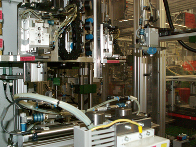
The geared motor is automatically removed from the indexing rotary table and placed on a pallet. All processing data is documented by a data block on the pallet. Defective parts are automatically sent to an integrated repair station.


